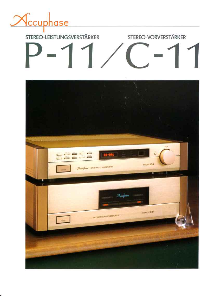
ACCUPHASE – PRE C 11 E FINALE P 11
ACCUPHASE – PRE C 11 E FINALE P 11

The stereo preamplifier which concentrated the development technical capabilities accumulated over the element and many years
Quotazione

Quotazione: C11 eur 700/900
Quotazione: P11 eur 1000/1200
PREAMPLIFICATORE C 11 E FINALE P 11
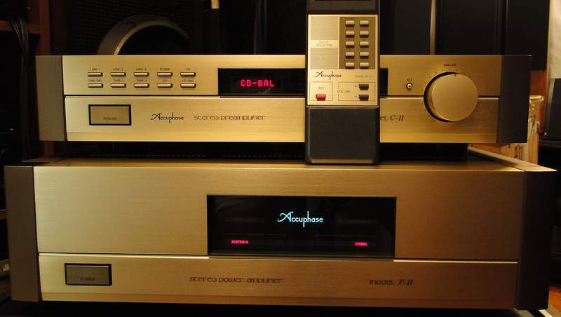
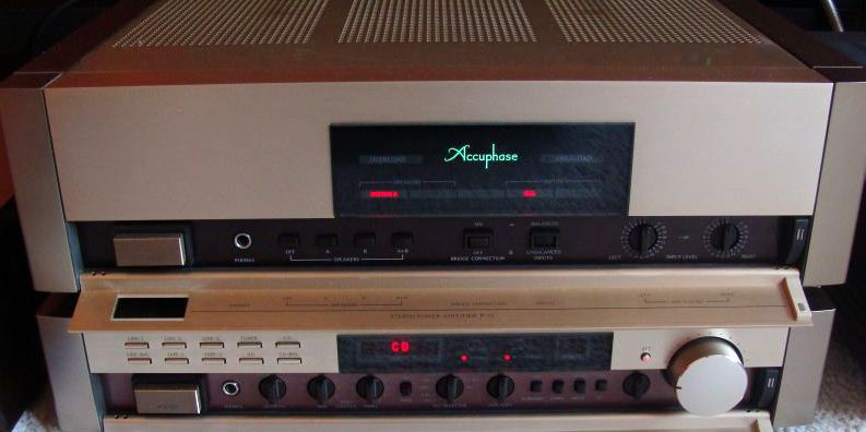
Pre e finale della rinomata casa nipponica che mantengono le caratteristiche distintive del marchio: le sonorità ambrate e la notevole potenza del finale (120 watt per canale su 8 ohm), forniscono riproduzioni timbricamente vellutati ma generosi nell’erogazione della potenza. Il finale può essere collegato a ponte (mono) così da erogare 340 watt su 8 ohm.
|
The stereo preamplifier which concentrated the development technical capabilities accumulated over the element and many years which were selected carefully, and was developed.
The balance input-and-output circuit is carried.
The dregs cord difference input and Class A push pull output stage are adopted as the high level flat amplifier handling signals other than an analog disc, and many characteristics are elaborated in it.
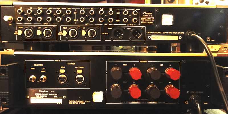
Moreover, the XLR type balance connector is carried in this amplifier portion at input and output, and ideal balance transmission is possible.
Equalizer amplifier is equipped with the input circuit for exclusive use in accordance with the cartridge of MC type and each MM model.
At the time of MM input, the FET Para input circuit which can maintain high input impedance over all the frequency bands is adopted in consideration of the Output voltage/Output load impedance of MM cartridge being high.
Moreover, since signal voltage is low, it thinks that a S/N improvement is important at the time of MC input, and it constitutes the input circuit from a small element of peculiar noise selected carefully.
These changes are performed by the relay and the change of the amplification degree which suited MM/MC simultaneously with it is also performed.
Since a straight signal course is constituted at the shortest, a relay is installed in a signal course required for a change, and it is changing by the logic relay control system which controls a relay electronically.
At this time, consideration is carried out also to the quality of the important relay, and the encapsulated type relay developed especially as an object for audios is adopted. A contact is a crossbar twin system and has acquired low contact resistance and high durability.
Input sauce and volume control can be performed now with attached remote control.
In this case, in order to prevent sound quality degradation occurring, the input change considered it as the system which changes a relay electronically, and volume control has also adopted the system which sound quality degradation makes rotate little manual volume by a motor.
The tone control for which the added type filter which was excellent in the characteristic was applied to tone control is developed and carried.
It passes straight, and if needed, an original flat signal is another, and makes the characteristic, and the principle of this tone control serves as a system adjusted from a flat signal, and is advantageous in sound quality.
Moreover, in order to think sound quality as important, it is used combining a quality element, and also an ON-OFF switch is formed, and a circuit is passed at the time of OFF.
The loudness Compensation is carried in order to rectify thinking that the quantity of low-pitched sound decreased at the time of small volume by man’s hearing characteristic.
The characteristic is being interlocked with volume control volume and controls the amount of reinforcement automatically.
It is also possible to carry the recording selector and to record another sauce during viewing and listening.
|
Specifications C 11 |
| Form | Stereo preamplifier | ||||||||||||
| Frequency response |
|
||||||||||||
| THD | 0.005% (with all the input terminals) | ||||||||||||
| Input sensitivity (rating / 0.5V output)/impedance | Balanced: 126mV/31.5mV/40kohm (20kohm/20kohm) Unbalanced: 126mV/31.5mV/20kohm AD MM: 4.0mV/1.0mV/47kohm AD MC: 0.13mV/0.032 mV/100 ohms |
||||||||||||
| An Output power/impedance | Balanced Output: 2.0V/50 ohm (25ohm/25ohm), a XLR connector Unbalanced Output: 2.0V/1 ohm, a RCA phono jack Tape Rec: 126mV/200 ohm, a RCA phono jack (at the time of AD input) |
||||||||||||
| Headphone jack | Conformity impedance: 4ohms – 100ohms | ||||||||||||
| S/N ratio (at the time of a rated input S/N /EIA S/N) | Balanced:97dB/91dB Unbalanced:110dB/91dB AD MM:90dB/84dB AD MC:74dB/83dB |
||||||||||||
| Input conversion noise | Balanced:-115dBV Unbalanced:-128dBV AD MM:-138dBV AD MC:-152dBV |
||||||||||||
| Maximum-except-take-off level (0.005% of a distortion, 20Hz – 20kHz) |
Balanced Output: 8.0V, a XLR type connector Unbalanced Output: 8.0V, a RCA phono jack Tape Rec: 8.5V, a RCA phono jack (at the time of AD input) |
||||||||||||
| The AD maximum inlet pressure (1kHz, 0.005% of distortion) | MM Input:270mV MC Input:8.5mV |
||||||||||||
| Minimum load impedance | Balanced Output: 600ohms Unbalanced Output: 1kohm Tape Rec: 10kohm |
||||||||||||
| Tone control | Bass: 300Hz, ±10dB (50Hz) Treble: 3kHz, ±10dB (20kHz) |
||||||||||||
| Gain |
|
||||||||||||
| Loudness Compensation (Volume-30dB) | +6dB(100Hz) | ||||||||||||
| Subsonic Filter | 17Hz, -12 dB/oct | ||||||||||||
| Attenuator | -20dB | ||||||||||||
| The semiconductor used | Transistor: 37 pieces FET: 16 pieces IC: 33 pieces Diode: 59 pieces |
||||||||||||
| Power source | AC100V/117V/220V/240V, 50Hz/60Hz | ||||||||||||
| Power consumption | 28W | ||||||||||||
| Dimensions | the width 445x height 95(piece — it includeds) x depth of 325mm | ||||||||||||
| Weight | 9.3kg | ||||||||||||
| Attachment: Remote commander RC-3 | |||||||||||||
| Remote control system | Infrared pulse system | ||||||||||||
| Power source | DC3V | ||||||||||||
| Battery | SUM-3(IEC name R6) 2 piece | ||||||||||||
| The maximum Dimensions | Width 64x height 149x depth of 18mm | ||||||||||||
| Weight | 140g (Battery includeded) | ||||||||||||
|
Description P 11 |
Stereo power amplifier which aimed at improvement in low impedance drive capability which sends in sufficient energy for a speaker not only with basic engine performance, such as a frequency response, a distortion, and S/N, but complex nature.
The output stage constitutes the large-sized output transistor of Pc(collector loss)130W from a 3 parallel push pull, and has gained the output stabilized by this also at the time of low impedance.
Moreover, the original power MOS FET of only an Accuphase is adopted as a drive stage as an electric power element which was excellent in the characteristic of bearing the high voltage.
The buffer stage is prepared in order to prevent interference with the preamplifier which is making the differential amplification stage take charge of voltage magnification of the preceding paragraph, and is connected in front of this stage, and an input level control.
The cascode system by FET is adopted as this buffer stage, it excels in the high frequency characteristic, and operation stabilized also in a large change of input impedance is carried out.
The large-sized toroidal transformer which was excellent in rate of change is adopted as a power-source part, and margin sufficient also at the time of the maximum except take-off is given to it.
Moreover, in order to prevent the mutual intervention in each stage, it has supplied and separated into an output stage and each preceding paragraph from the winding wire with which the transformer became independent. Furthermore, the preceding paragraph carries out right and left to independent composition with an exclusive commutator and a filter, and is suppressing interference of the order stage and the right-and-left channel to the minimum.
The incoming signal has adopted the direct connection system inputted direct.
When the large preamplifier of direct-current drift etc. is connected, it is amplified and it appears in an output, and in order to prevent damaging a speaker, while having adopted direct-current servo system and omitting a direct current, direct-current drift of the amplifier by a temperature change itself is stabilized.
Use is possible with bridge connection also as monophonic power amplifier in which a more powerful output is possible.
Bridge connection is inputting the signal of 180 degrees (negative phase) of phase difference in the same magnitude as the same amplifier, and taking out sy copy power from the output end of both amplifier,It is equivalent to carrying out the push pull drive of two sets of the amplifier with the system that the twice as many output in the 4-ohm load at the time of a stereo drive as this will be obtained at the time of 8-ohm load.
Usually, although a phase inversion circuit is inserted in one amplifier at the time of bridge connection, the polarity of the difference input circuit of two amplifier is used, and the ideal change circuit which inserts no amplifier consists of P-11.
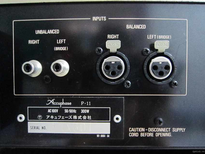
The balance input full-scale besides the usual phono jack input is carried.
The balance input circuit of P-11 is considered as the ideal composition which inputs a signal into plus of a difference input circuit, and a minus input as it is.
Moreover, the 1dB step twin Attenuator with few interlocking errors is adopted as the level control which must be inserted in each of plus and minus in this case.
Two output terminals are carried so that 2 sets of speakers can be driven.
It is controlled by the large current relay which became independent, respectively, and in A+B, two lines become parallel connection and a bi-wiring speaker can be connected.
The overload indicator which tells a maximum-except-take-off level is carried.
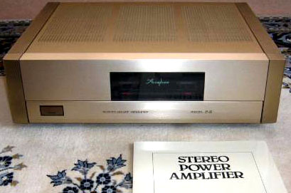
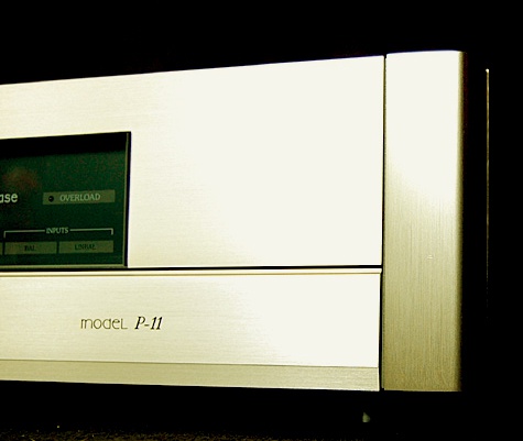
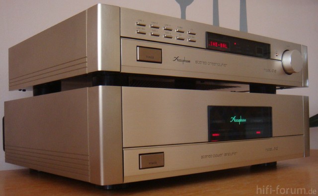
Based on the panel of champagne gold scratch hair line finishing which is the keynote of an Accuphase, a display with thick glass is prepared in the center, and it has become the design which processed both sides by the thick metal end block.
|


